How to Wire Can Lights to a Two Way Switch
ALL of these circuits can be built using batteries (dry cells) only !!!
If yous have no experience with wiring OR if you lot want suggestions
on what supplies to buy, click hither.
As is the instance with the "Lincoln Cent Project", electricity is another good instance of science being office of our everyday lives. Look around y'all. Your television, your clock radio, the estimator y'all are using and many other electrical appliances are all utilizing electrical power.
To explain things as briefly every bit possible, electricity is a flow of electrons. Substances that permit electrons to flow freely are chosen conductors and those that don't are chosen insulators.
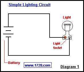 Diagram number 1 illustrates an extremely simple circuit. (For the moment, ignore the dotted line and the points A and B). The battery is represented by iv horizontal lines. Starting from the negative cease (-) of the battery, electrons "circle" through i wire, laissez passer through the lite bulb, pass through the other wire and so return to the battery (+), thereby completing the circuit. See? Quite uncomplicated.
This is all well and good but in that location are 2 drawbacks to this circuit 1) the low-cal always stays on and 2) the power is constantly beingness used. How can we plow the light seedling 'off'? Well, we could unscrew the seedling from the socket but in the real world this is very inconvenient. (Light bulbs are inside fixtures, on ceilings and then on). Possibly nosotros could disconnect the power at the source. This too is very inconvenient. You would have to go downwards to your basement to shut the power off. Or - much more than unsafe - you would take to disconnect the electric supply wire earlier it reaches the light socket.
Is there a rubber fashion to interrupt the electron flow without physically touching the wire? Sure. It is called a SWITCH !!!
The inside of a typical household wall switch has a strip of metal (B), making contact with point 'A', completing the excursion and thereby conducting electricity to the light. This would patently be the 'ON' position. When the insulated lever is moved downwardly to the 'OFF' position, information technology pushes the metal strip abroad from betoken 'A', breaking the excursion and turning the calorie-free 'OFF'.
This type of switch (having a lever which "flips" information technology on and off) is called a toggle switch.
Because of being well-insulated and mounted in a box, household switches are a safe style for turning electric devices on and off.
Finally, let'due south talk almost that dotted line in Diagram one. Now what would happen if point A and indicate B were to bear on OR if they were connected with a wire or other conductor? Well, the light bulb would turn 'off', the wires and the bombardment would get very warm very fast and the electrons would simply travel from the battery to point A to signal B and so back to the bombardment. Notice that in this new circuit , the electrons are traveling a path (or circuit) that is shorter than the original one. Hence y'all have just learned what a "short excursion" is and how its name is derived! Short circuits are unsafe. They crusade wires to heat, circuit breakers to 'trip' and can even start fires.
There are many different types of switches: toggle, rotary, pushbutton, "rocker", "pull-chain", slide, magnetic, mercury, timer, voice-activated, "touch-sensitive", and many others. Heck, even the Clapper™ is some other blazon of switch !
The "knife switch" (rarely seen nowadays) is the type that most easily demonstrates the performance of a switch. Old sci-fi movies ("Frankenstein (1931)" or "Young Frankenstein (1974)", for example), fabricated all-encompassing utilize of these switches in the laboratory scenes.
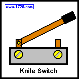
Today, use of knife switches has been confined to 1) heavy-duty industrial applications and 2) demonstration purposes - scientific discipline projects for example. The knife switch has a metal lever, insulated at the 'free end' that comes into contact with a metal 'slot'. Since the electric connections are exposed, knife switches are never seen in household wiring.
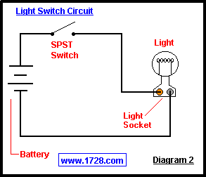 Referring to Diagram 2, the wiring is very like to Diagram ane except a switch has been added. Compare this to the Typical Household Light Switch diagram. Pretty much the same principle at piece of work wouldn't you say? This type of switch is a Single Pole Single Throw (or SPST). This ways that information technology controls 1 wire (pole) and it makes ane connectedness (a throw). Yes, this is an on/off switch, simply a 'throw' only counts when a connectedness is made. 'Off' is not considered a 'throw'. Also notice that only i wire has to be switched. (Post-obit the circuit from one end of the bombardment to the other y'all tin can run across why this is and then).
As it is, this circuit lonely could be your science project. A variation could be substituting a push-push button switch and putting a 'buzzer' or 'doorbell' where the calorie-free is. At present you have a good sit-in of how a doorbell is wired. Pushbutton switches are usually "momentary on". That is to say the connection is made only when you press the button. In that location are "momentary off" pushbutton switches, but using i in a doorbell excursion would hateful the bell would be constantly on until someone pressed the button. Impractical don't you remember? (The comedian Tim Conway joked that his begetter wired a doorbell in just this way. When there was silence someone would say "Hey somebody'south at the door").
A practical utilise of the momentary off switch is the "mute push button" on your phone. If a momentary on switch were used, it would be very annoying to press the push button constantly as you talked and released information technology only for muting. This shows how each type of switch has its specific applications.
 The burglar alarm circuit at left employs magnetic switches. These switches and their associated magnets are by and large mounted on doors and windows. Detect that Switch 1 and Switch 2 are wired in series. Both switches must be airtight in order for the circuit to exist complete and for the bulb to light. (This would indicate the 'armed' status of this burglar alarm.) Magnetic switches come in two varieties - "Ordinarily Closed" and "Unremarkably Open up". These two terms describe the state of the switch when it is Not being controlled by the magnet. The switches in this diagram are the "Commonly Open" blazon and considering the magnets are far enough away, the switches are in the 'open' state. If the magnets were brought closer, the bulb would proceed and the circuit would be "armed". At this point, moving either magnet would brand the bulb get out and the alert would exist triggered. (For the sake of simplicity, the activated alarm excursion has not been drawn). An of import point to note is that cut the wires at any point would also make the bulb get out and trip the alarm.
The next type of switch (no diagram) is the Double Pole Unmarried Throw (DPST). These switches are used when there are 2 'live' lines to switch but tin can merely turn on or off (unmarried throw). These switches are non used much and are usually found in 240 volt applications.
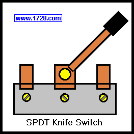
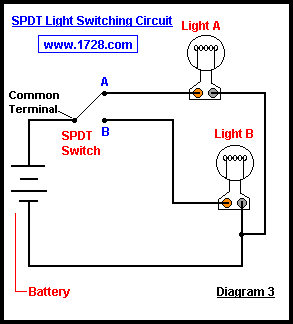 Diagram 3 makes use of the Single Pole Double Throw Switch. The common terminal is the middle final in the SPDT Knife Switch or if yous are using a household switch, it would be the brass colored final. (the other two would be argent colored). This circuit conspicuously demonstrates what happens when the SPDT switch is moved back and forth. Light A goes on and B goes off, B goes on and A goes off and and then forth. You lot tin meet that this popular switch would have many practical applications: the transmit/receive button on a "2-way" radio, the "loftier/low beam" switch for your car headlights, the pulse/tone dialing switch on your telephone, and and so on.
If you lot are using the SPDT pocketknife switch, you lot have a "center off" position, which an ordinary wall switch would Non accept in which case you will need to add an SPST switch for shutting this circuit off. (In electronics work, many SPDT switches take a middle position in which the electricity is turned off to BOTH circuits. It is an SPDT heart off switch. Also, some electronic SPDT switches accept a "centre on" position. The best example of this type of switch is the "pickup" selector on an electric guitar which can choose the rhythm, treble or both pickups for 3 varieties of sounds).
Diagram 4 (below) depicts what is probably the most common use for the SPDT switch - the iii way low-cal switching excursion. Electricians incorrectly call the SPDT switch a "3 style switch". The proper terminology should be "iii last switch". However the term 3-way switch has stuck and it's a misnomer we'll simply have to alive with.
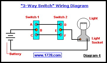 And then, how does this work? Let's say that Switch one is at the bottom of a stairway and Switch ii is at the tiptop. Suppose Switch 1 is in a 'down' position (B & C continued) and Switch 2 is in an 'up' position (D & E connected). The light bulb is off. Now someone comes to the bottom of the stairs and flips Switch 1 'upward'. If you follow the circuit you can see why the light bulb would now plow on considering A & B and D & E are connected. When the person reaches the peak of the stairs, Switch 2 is flipped 'downward', E & F are now connected and so the low-cal seedling goes off. Another person shows upwardly at the bottom of the stairs and flips Switch 1 'down', connecting B & C thereby turning the light on again. The person reaches the top of the stairs, flips Switch ii 'upwards' connecting D & East and the low-cal seedling goes off. Observe that in the case of the second person, a downstroke turns the bulb on and an upstroke turns the bulb off. If y'all have such switches in your house OR if you have purchased household wall switches for this circuit, you now see the reason why they do Non have the words on and off printed on them.
Don't you call back this switching organisation would make a not bad science project?
A elementary manner to think of this switch is imagining ii SPDT switches next with the 'handles' attached to each other. Perhaps the about popular utilize for this switch is 'stage or polarity reversal'. So, how does the DPDT switch achieve this? First, you take to wire the 2 'superlative' and 2 'bottom' terminals in a 'criss-cross' fashion. The top ii terminals become the input and the eye two terminals become the ouput. At present, referring to the bottom left diagram, the switch is in the 'up' position, W & Y are connected, every bit are X & Z. The polarity is maintained because the input and output are straight connected. No problem seeing that correct?
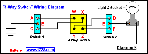
Another important (though not very mutual) utilize is to put this switch between 3-way switches and so that the same lite may exist switched from many different locations. Referring to Diagram iv, if A & B and E & F were connected, the seedling would be off. Just now remember of the wires going from A to D and C to F. If their connections were reversed, ( A to F, C to D), the light bulb would turn on again. And then, how would we be able to opposite the polarity of these 2 wires? Past using the polarity reversing switch ! (Meet Diagram 5 below).
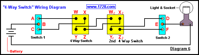
Also,you don't take to limit yourself to using only 1 iv-manner switch. If y'all were to attach a second iv-way switch from the Y and Z terminals of the first switch to the Due west2 and Ten2 terminals of the second switch, you could accept the aforementioned low-cal switched from a 4th location. (See Diagram 6).
Adept luck with the project !!!
Copyright © 1999 - 1728 Software Systems
Source: https://www.1728.org/project2.htm
0 Response to "How to Wire Can Lights to a Two Way Switch"
Post a Comment